Tutorial: Render subdivision modifier wireframe in Blender with Geometry Nodes 🔗
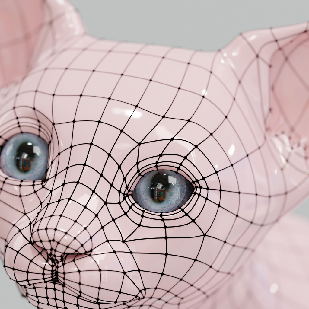
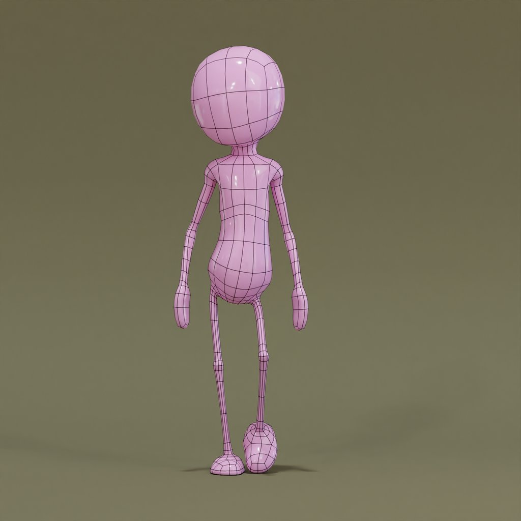
Blender's Geometry Nodes offers a powerful way to create wireframe visualizations of your 3D models that incorporate subdivision surface modifiers. This tutorial will guide you through the process of rendering a clean wireframe that showcases both the original edges and vertices of your model and the effects of the subdivision modifier.
Option 1: Use pre-made assets 🔗
If you prefer not to follow a detailed procedure, you can download the template directly from BlenderKit and apply the geometry nodes modifier to your model. Alternatively, you can download one of the prepared scenes for this purpose.
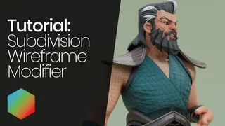
Option 2: Follow our tutorial and learn more about Geometry Nodes! 🔗
Option 3: Follow this article 🔗
Step 1: Replicating Subdivision Modifier 🔗
- Add a new Geometry Nodes modifier on your mesh (delete the Subdivision Modifier first)
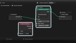
- Add a subdivision surface node and set the subdivision to 2.
- Add an Input > Named Attribute node, select 'crease' in the Name field, and connect it to the Edge Crease input of the Subdivision Surface node.
Step 2: Visualize Original Edges 🔗
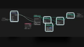
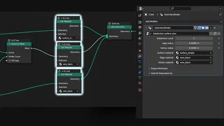
1. Create a new branch after the subdivision by adding Mesh to Curve, Curve to Mesh, and Join Geometry nodes.
2. Add a Curve Primitives > Curve Circle node and connect it to the Profile Curve of the Curve to Mesh node. Set the Curve Circle radius to 0.001 and the resolution to 8.
3. Add a Capture Attribute node before the subdivision node. Set the first value to Boolean, the second value to Edge, and check the 'value' field
4. Connect the 'Attribute' output of the Capture Attribute node to the Selection input of the Mesh To Curve node. Now only the original edges are visible.
Step 3: Visualize Original Vertices 🔗
1. Add another Capture Attribute node behind the first one. Set it to Integer and the second value to Point.
2. Add an Input > Index node and connect it to the Value input of the Capture Attribute
3. Add Mesh Primitives > Icosphere and Instances > Instances on Points nodes. Connect the Subdivision Surface output to the Points input of the Instances On Points node, and the Mesh output of the Ico Sphere to 'Instances'. Connect the Instances On Points geometry output to your Join Geometry node. Set the radius of the Ico Sphere node to 0.2.
4. Connect a Utilities > Compare node to the Attribute Output of the Capture Attribute node. Set the first field (type) to Integer and the second field (function) to Equal. Add another Input > Index node and connect it to the other input of the Compare node. Connect the output of the Compare node directly into the
Selection Input of the Instances on Points node.
Step 4: Apply Materials and Smooth Shading 🔗
1. Add 3 Material > Set Material nodes, one for each part of the mesh: surface, edges, and vertices. Assign any materials you like. Simple colors usually work best in this case.
2. Add a Mesh > Set Shade Smooth node to finalize the look.
Conclusion:
Congratulations! You've successfully created a wireframe visualization that emphasizes the original edges and vertices of your model while showcasing the effects of the subdivision surface modifier. Feel free to customize the input parameters, such as the subdivision level, sphere radius for vertices, and edge thickness. Compare your results with the provided asset to ensure that you've followed the tutorial correctly. Happy rendering!
